

ThingsInNet Actuating Dev Kit: Sample Code That Brings It to Life
If you’ve ever built IoT, robotics, or embedded system prototypes with loose jumper wires and separate relay modules, you already know the pain: unstable connections, messy wiring, and last-minute failures during demos or presentations. The ThingsInNet ESP32 Universal IoT Dev Kit – Actuating is built to remove that friction and give you a clean, reliable actuator-focused platform from day one.
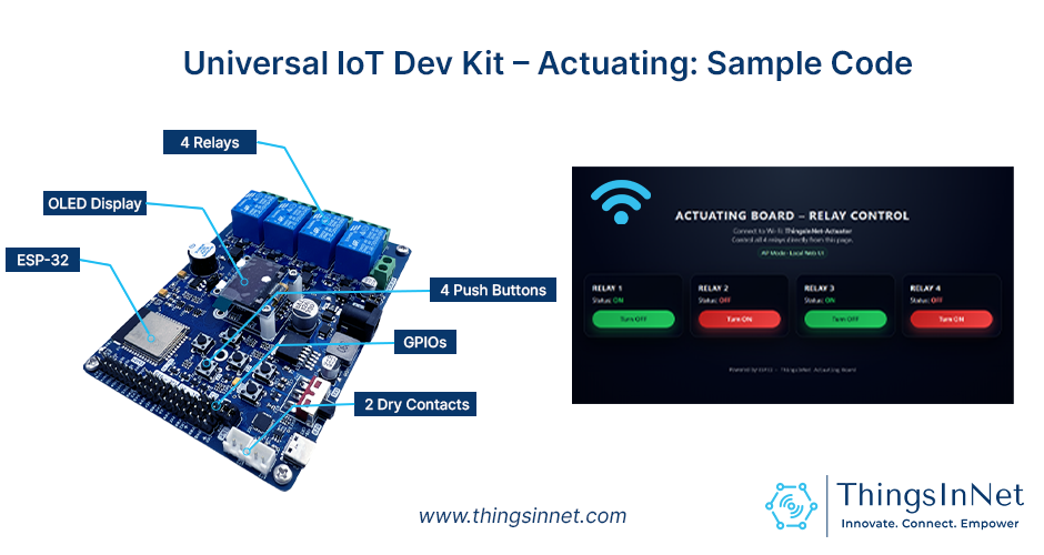
This board is designed using an ESP32 module with Wi-Fi/Bluetooth, and it includes four integrated relays, OLED display, buzzer, and push buttons, plus plenty of GPIO expansion pins, I2C and power options, so you can go from “idea” to a working control system quickly.
And the best part: it ships with a default Sample Code that instantly turns the board into a Wi-Fi relay controller with a modern dashboard UI.
Meet the board: what you get on hardware
The actuating kit is built for real actuator work:
- ESP32 MCU (ESP-WROOM-32D-N8) with integrated Wi-Fi + Bluetooth
- 4 integrated relays (each rated 250V/10A AC, 30V/10A DC) with opto-isolation to protect the MCU from back-EMF and noise
- 0.96″ SSD1306 OLED (128×64, I2C) for live device status and onboarding info
- Buzzer (GPIO26) for audible alerts
- User LED (LD2 / GPIO2) for custom indications (Wi-Fi status, alarms, etc.)
- 4 user push buttons (ready for local control / triggers)
- Dry contacts (FL1/FL2) and expanded GPIO/I2C headers for sensors and extra controls
- 8–24V input power (ideal for field deployments)
- Programmable using Arduino IDE, MicroPython, or ESP-IDF
This board is also positioned for long-running R&D and real deployments (not just quick prototypes).
What does the Sample Code do?
It comes with ready-to-run starter firmware. You can use it as it is, or customize it into your own controller. Once powered on, the board works as a self-contained relay controller. Users can connect to the device and control appliances instantly with little to no coding required.
1) The ESP32 creates its own Wi-Fi network (AP Mode)
Your phone/laptop connects directly to the board’s hotspot (example: TIN-Actuating). No router is required. Then you open a browser and control relays locally.
2) A built-in web dashboard controls 4 relays

The code hosts a small web server on the ESP32. The dashboard (Figure above) shows Relay 1–4 with clear ON/OFF states and control buttons.
3) Live device feedback via OLED
- If no one is connected, the OLED shows onboarding info (SSID, password, and IP).
- If a client is connected, the OLED switches to a relay status screen (Relay 1–4 ON/OFF).
4) “Heartbeat” detection (knows when the user disconnects)
The web page sends a small ping (/alive) every few seconds. If the ESP32 stops receiving it, it marks the client as disconnected and returns to the info screen.
Users can update the code to keep the last relay settings running on the board for real-world, continuous operation.
5) Buttons + buzzer for quick local interaction
Pressing any of the onboard push buttons triggers the buzzer and LED as a simple local alert (useful for demos, alarms, or manual triggers).
Why is this Sample Code useful (not just a demo)?
This default firmware is a strong starting point because it’s already a complete pattern you can reuse:
- Local-first control (works even without internet)
- Simple API endpoints that are easy to integrate (/state, /toggle)
- UI + status feedback (dashboard + OLED)
- Expandable: you can add timers, schedules, MQTT/Firebase, sensor rules, safety interlocks, and more—without rewriting everything
Quick start (user-friendly flow)
- Power the board (external supply is recommended for stable use).
- Connect your phone to the board’s Wi-Fi SSID shown on the OLED.
- Open your browser and go to the device IP (commonly 192.168.4.1 in AP mode).
- Toggle Relay 1–4 from the dashboard.
- Watch relay status appear on the OLED when you’re connected.
Customize it for your project (recommended upgrades)
The Sample Code is mainly for testing the board’s relay functions, and users are encouraged to edit and customize it to suit their requirements. In some cases, they may also add extra modules such as RTC, an ADC, or additional sensors, depending on their application.
1) Make it your product (branding + access)
Change:
- Wi-Fi SSID / password
- Page title and labels (e.g., “Pump”, “Light”, “Gate”, “Alarm”, “Valve”)
- Add a “Device Name” or “Location” on the OLED
Example (Edit the SSID and password in the code):
const char *ap_ssid = ” TIN-Actuating “;
const char *ap_password = “12345678”;
2) Match your wiring (relay logic & pins)
The board relays are specified as Active Low in documentation mapping. So you can keep the default logic, or flip it if your relay hardware differs.
Pin mapping reference (from the board documentation):
- Relay 1: GPIO25, Relay 2: GPIO14, Relay 3: GPIO16, Relay 4: GPIO17
- Buttons: GPIO34/35/39/36
- OLED: SDA GPIO21, SCL GPIO22
- Buzzer: GPIO26, LED2: GPIO2
3) Use it across industries
The board is designed for a wide range of applications, from smart farming and environmental systems to robotics and security.
That means it can be installed in applications including, not limited to:
- A greenhouse pump/light controller
- A smart door/gate actuator controller
- A lab automation relay panel
- A field-deployable alarm + cutoff unit
Closing Remarks and Notes
The Sample Code is not “just a sample.” It’s a ready-made foundation: Wi-Fi + dashboard + relay API + OLED all built into a single sketch. With a few edits, users can turn it into their product: a controller for pumps, lights, solenoids, alarms, gates, or any actuator-based IoT system.
- External power is recommended for stable operation, even if USB can run it.
- Relays can directly control high power devices up to 600W and always follow safe electrical practices (enclosure, contactors, proper wiring, and protection).
- For AC mains wiring, use proper enclosures and safety protection, and follow local electrical standards.
- Download the Sample Code, customize it, and build your own actuator controller in minutes.
- The components can be upgraded or removed for custom builds, and users can request customized versions.
- If you need customized firmware build for your exact relay/sensor set and workflow, ThingsInNet team can tailor it on request.